
Framework overview
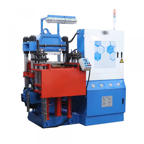
This guide gives a step-by-step framework for engineers who must specify tyre bladder injection machines. Start with performance targets, then match machine capacity, control systems, and service support. Early on you should check related equipment — for example a rubber vulcanizing machine in your line — because curing constraints affect cycle design and clamp requirements.
Step 1 — Define performance targets
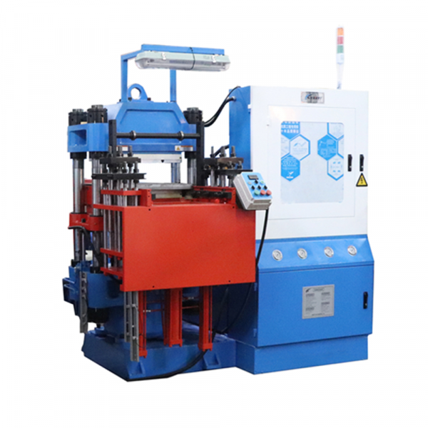
Write clear numbers for clamping force, shot accuracy, and cycle time. Use measurable units: kN for clamping force and grams or cc for shot size. Set tolerance bands for shot accuracy and dimensional repeatability of the bladder after molding. Tie those targets to downstream process needs such as vulcanization dwell time and mold cavity cooling rates. Real-world anchor: many suppliers in Bandung’s rubber cluster link machine specs to ISO 9001 factory processes to keep consistency across shifts.
Step 2 — Machine capacity and interface
Match platen size and clamping force to the mold footprint and expected injection pressure. Specify platen parallelism and tie-bar layout so the mold cavity receives uniform pressure. Include injection system type — reciprocating screw or plunger — and confirm shot size control (volumetric shot vs. weight-based dosing). Also plan for reliable mold alignment and quick-change fixtures to reduce downtime.
Step 3 — Controls, sensors, and data
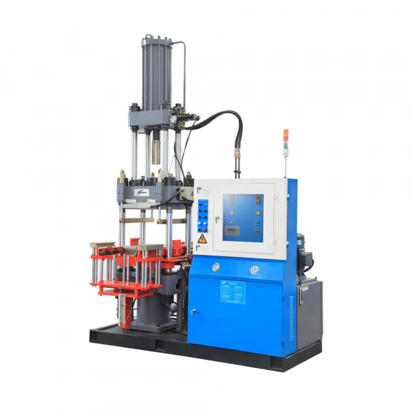
Insist on closed-loop control for shot delivery and pressure profiling. Use sensors on barrel pressure, nozzle position, and platen displacement to monitor shot accuracy in real time. Collect cycle logs to validate repeatability and to spot drift before quality escapes. Good control systems reduce scrap and stabilize cycle time.
Common mistakes to avoid
Engineers often under-spec clamping force and then compensate with slower cycles — that costs throughput. Another trap is trusting nominal shot volume without validating for changing raw-material viscosity. Don’t ignore peripheral equipment: uneven heating in a vulcanizing press or poor mold cooling maps will hide as shot variation. Plan service access and spare parts lists up front — a fast replacement reduces production loss.
Supplier selection and verification
Evaluate suppliers on three fronts: machine test data, shop acceptance testing, and after-sales support. Require injection trials using your compound and mold geometry. Visit references and inspect running lines where possible. If you need a full press partner, consider an established rubber vulcanizing press machine supplier who understands both molding and curing stages — cross-domain experience matters.
Checklist: what to specify in contracts
Include: guaranteed clamping force at defined platen separation, shot accuracy range, servo response time, spare-parts lead times, and acceptance criteria for first articles. Add a clause for training and remote diagnostics. Make performance acceptance objective, not subjective.
Summary of practical steps
Begin with target metrics. Match machine mechanics to mold geometry. Lock in control and sensor specs. Verify with trials. Protect production with spare parts and service. These steps connect technical targets to real line outcomes without unnecessary complexity — and they make procurement decisions defensible.
Advisory: three golden rules
1) Prioritize measured repeatability over highest theoretical clamping force — consistent shot accuracy wins more than peak capacity. 2) Require on-material commissioning: accept the machine only after it runs your compound through a full production cycle with documented results. 3) Specify remote diagnostics and guaranteed spare-part lead times to keep uptime above target.
Closing
Follow these rules and your tyre bladder program will hit targets with fewer surprises. HWAYI brings combined expertise across molding and vulcanizing to make that practical — trust built on tested machines and service. –