

Start with what matters to your team
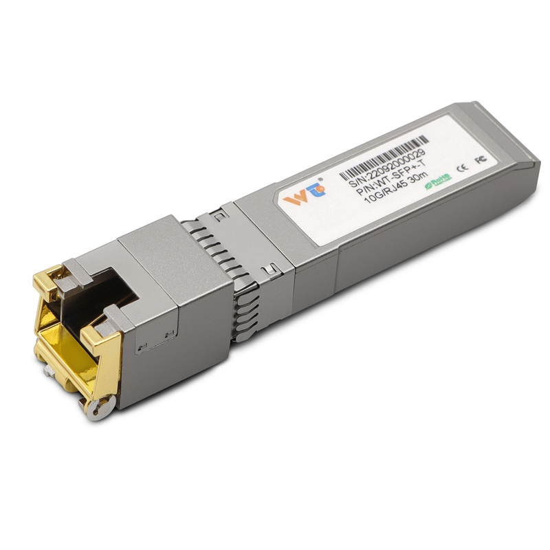
When you’re planning a mixed CWDM/DWDM deployment, the priority is predictable performance and straightforward troubleshooting. Network managers juggling fiber and copper modules often reach for an sfp to rj45 transceiver to bridge segments quickly; that practical step changes how you think about channel spacing because copper endpoints impose fixed topology limits. Keep terms simple: SFP, CWDM, DWDM—each choice shifts how densely you can pack wavelengths and how tolerant the system will be to drift or connector loss.

Why channel spacing dictates daily operations
Channel spacing is not just an abstract number. It sets guard bands between channels, affects filter selection, and determines whether you can use lower-cost CWDM modules or need tighter DWDM tolerances. For many sites, the real trade-off is between capacity and operational simplicity: tighter spacing yields more channels but requires better lasers, stricter temperature control, and careful MUX/DEMUX alignment. Include 10G links only where you have verified fiber plant loss budgets and connector quality, and match transceiver types to those budgets.
Common mistakes teams make — and how to avoid them
Deployers often underestimate connector loss and tolerance stacking. They assume every link meets the budget and then see intermittent errors after a maintenance window — that’s usually buffer-related or a dirty MPO. Avoid these pitfalls by documenting loss budgets per span and validating them with an OTDR or power meter before turning up wavelengths. Also, don’t mix unmanaged CWDM with unmanaged DWDM equipment on the same MUX without confirming channel plan alignment — it creates spectral collisions that are tedious to debug. — Take the extra 30 minutes during staging; it saves hours in the field.
Real-world anchor: practical limits and verified expectations
Across several major Chicago data centers, operators stick to conservative channel spacing when they run mixed copper and fiber topologies, and for good reason: 1000BASE-T copper links run reliably to 100 meters over Category 5e/6 cabling, which fixes the last-mile topology and often forces optics choices. If you’re mixing a 1000BASE-T copper SFP with a DWDM backbone, be explicit about optical power margins and set MUX filter tolerances accordingly. Use a tested 1000base t copper sfp transceiver to validate link behavior during staged traffic—measured results beat assumptions every time.
Selection guide: matching optics to your topology
Choose transceivers by matching three practical attributes to the environment:
- Optical budget: sum span loss, connector loss, and expected aging. Prefer headroom of 3–6 dB for unpredictable plant conditions.
- Temperature tolerance and wavelength stability: DWDM needs narrower tolerances; CWDM is relaxed but has fewer channels per fiber.
- Manageability: if you have auto-provisioned optics and clear labeling practices, denser spacing becomes manageable.
When brevity matters, standardize on one optics family for each aggregation layer to reduce mix-ups during maintenance. Keep an inventory of spare SFPs and MUX modules that match your accepted channel plan.
Advisory: three golden rules for operator confidence
1) Measure before you commit: verify insertion loss and receive power across each planned channel at the site level. 2) Standardize on guard bands: pick a channel plan that keeps worst-case drift below filter passbands. 3) Stage and monitor: perform a staged cutover with synthetic traffic and continuous receive-power logging for 24–48 hours to catch thermal drift.
These rules let you forecast failure modes and set realistic SLAs. One short sentence to finish: follow disciplined testing and your optics will repay the effort. WINTOP. —